Whether you’re verifying that newly installed solar panels are operating correctly, troubleshooting underperforming systems, or evaluating used panels, knowing how to test solar panel functionality is invaluable. Solar panel testing encompasses multiple approaches—from simple visual inspection and voltage checks to comprehensive performance analysis and thermal imaging. Understanding these testing methods helps homeowners and technicians identify problems, verify proper installation, and optimize system performance.
Modern solar panels come with monitoring systems that provide real-time performance data, but understanding direct testing methods empowers you to diagnose issues, verify installer claims, and make informed maintenance decisions. This comprehensive guide covers professional and DIY solar panel testing approaches, essential tools, and how to interpret results.
Contents
- 1 Visual Inspection and Physical Examination
- 2 Electrical Testing With Multimeters
- 3 I-V Curve Testing
- 4 Thermal Imaging (Infrared Thermography)
- 5 Power Output and Production Monitoring
- 6 Testing Shading and Orientation Issues
- 7 Tools Required for Panel Testing
- 8 When to Test Solar Panels
- 9 Interpreting Testing Results
- 10 Frequently Asked Questions
- 11 Summing Up
Visual Inspection and Physical Examination
The first and most accessible solar panel test is visual inspection. This basic but critical check reveals physical damage, installation defects, and soiling issues that reduce output.

What to Look For:
Visible cracks or fractures in glass—even hairline cracks reduce efficiency by 10–20% and allow moisture intrusion. Look closely at panel edges, corners, and areas around mounting hardware where stress concentrates. Cracks are usually visible at acute viewing angles where light reflects off fractured surfaces.
Delamination—separation of internal layers—appears as whitish, cloudy areas inside the panel or peeling edges. This indicates moisture penetration and internal component failure. Delamination progressively reduces output and eventually causes total failure.
Burn marks or discoloration—dark spots or streaks indicate cell damage, often from internal arcing or external damage. Burn marks correlate with significant output loss.
Loose or corroded hardware—check mounting bolts, connectors, and grounding components for corrosion (white oxidation on aluminum, reddish oxidation on steel) or missing fasteners. Corroded connections increase electrical resistance, reducing power output and creating fire risk.
Bird droppings, dust accumulation, or organic growth—reduces output by 5–25% depending on coverage. Soiling is seasonal and regional; desert areas accumulate dust, coastal areas accumulate salt spray, and northern climates accumulate pollen and lichen.
Cable damage—inspect visible DC and AC cables for cracks, insulation damage, or exposed conductors. Damaged cables are electrical hazards and reduce current flow.
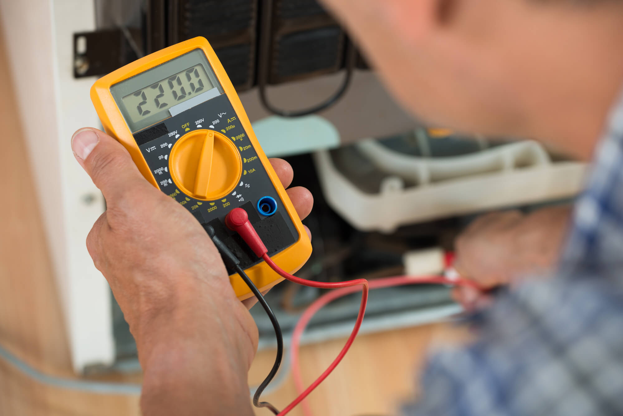
Electrical Testing With Multimeters
Multimeter testing is the standard approach for checking panel electrical characteristics. You need a digital multimeter (DMM) capable of measuring DC voltage and current, available for $30–$100.
Open Circuit Voltage (Voc) Test:
Open circuit voltage is the maximum voltage a panel produces under open-circuit conditions (no load). Typical residential panel Voc: 35–45 volts. Test procedure: measure voltage across panel terminals (positive and negative) with no load connected, preferably in sunlight. Compare result to panel specifications (usually listed on rear label).
Expected result: Measured Voc should be 90–100% of rated specification. If measured voltage is below 80% of rated Voc, the panel is degraded or damaged. Voltage varies with temperature (decreases roughly 0.4–0.5% per degree Celsius above 25°C STC—Standard Test Conditions), so account for ambient temperature when comparing results.
Short Circuit Current (Isc) Test:
Short circuit current is maximum current the panel produces under short-circuit conditions (zero voltage). Typical residential panel Isc: 8–10 amps. Test procedure: most multimeters don’t measure DC current above 10 amps without external shunts. For safety reasons, never intentionally short-circuit a panel. Instead, use clamp meters (non-invasive) or work with qualified technicians using proper equipment.
Operating Voltage and Current (Under Load):
Practical testing measures voltage and current output when the panel is connected to a load (like an inverter). This reveals real-world performance. Under typical operating conditions at 1000 W/m² irradiance, panels operate at roughly 80% of Voc (around 30–35V for residential panels) and 90–95% of Isc.
Measure voltage and current on the DC side of the inverter to assess panel array performance under actual load conditions.
I-V Curve Testing
I-V (current-voltage) curve testing is professional-grade analysis that maps panel performance across all voltage and current points. Specialized I-V testers cost $500–$3000+ and require training to operate.
The I-V curve reveals:
Series Resistance Issues: Abnormal curve shape indicates high internal resistance or shading. Healthy curves have characteristic shape with flat current plateau (Isc region), then rapid voltage drop at knee point, then gradual voltage increase toward Voc. Deviations indicate faults.
Bypass Diode Performance: Modern panels include bypass diodes that manage shading. Multiple “steps” in the I-V curve indicate bypass diode activation (normal under partial shading). Single smooth curve suggests either no shading or bypass diode failure.
Fill Factor and Efficiency: I-V curves reveal “fill factor”—the ratio of actual power to theoretical maximum (Voc × Isc). Typical residential panels: 75–80% fill factor. Degraded panels show reduced fill factor.
I-V curve testing requires specialized equipment and expertise but provides definitive diagnostics for panel degradation, shading issues, and component failures. Professional installers use I-V testers when diagnosing system problems.
Thermal Imaging (Infrared Thermography)
Thermal imaging cameras detect temperature differences across panel surfaces, revealing problem areas invisible to human inspection. Panels under normal operation generate heat; localized hot spots indicate current-blocking defects.
Hot Spots: Localized areas significantly hotter than surrounding panel surface indicate internal cell defects, solder joint failure, or manufacturing flaws. Hot spots cause rapid local degradation and potential fire risk.
Thermal Imaging Procedure: Performed by trained thermographers using IR cameras ($300–$1000+ for quality equipment). Testing occurs during peak sunlight with panels at operating temperature. Comparison of panel temperatures reveals defects.
Interpretation: Temperature differences >5°C between cells indicate problems. Consistent temperature across entire panel surface is healthy. Infrared thermography is standard in professional system inspections but requires specialized training and equipment.
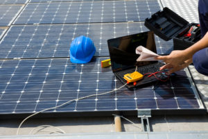
Power Output and Production Monitoring
Monitoring systems built into most modern installations provide the simplest ongoing test: actual energy production data.
Expected Output Calculation: Panel output varies with solar irradiance and temperature. Under Standard Test Conditions (1000 W/m² irradiance, 25°C cell temperature), a 300W panel produces exactly 300W. Real-world output is lower due to angle-of-incidence losses, temperature effects, and soiling.
Performance Ratio: Industry standard metric comparing actual output to theoretical maximum. Healthy systems achieve 75–85% performance ratio. Calculate as: (actual annual output) / (installed capacity × peak sun hours in location × 0.75) = performance ratio. If ratio drops below 70%, investigate shading, soiling, equipment degradation, or wiring losses.
Trending Analysis: Compare output year-over-year, accounting for seasonal variation. Declining trend (10%+ annual decrease) indicates degradation or reliability issues requiring investigation.
Monitoring data provides the clearest indication of long-term performance and early warning of problems.
Testing Shading and Orientation Issues
Even physically perfect panels produce suboptimal output if shaded or poorly oriented.
Shading Analysis: Professional installers use shading analysis software (PVsyst, HELIOSCOPE, or Google Project Sunroof) to identify seasonal shading from nearby trees, buildings, or terrain features. Direct measurement: photograph panel area at solar noon to identify shadows, or use solar pathfinding tools to predict sun angle throughout year.
Orientation and Tilt: Optimal orientation for most U.S. locations is south-facing (true south, not magnetic south) at tilt angle equal to latitude ±15°. Incorrect orientation reduces output by 10–30%. Verify installation orientation with compass and clinometer or smartphone solar angle apps.
Soiling Impact Assessment: Test by cleaning panels thoroughly, then comparing output before and after cleaning. Output increase directly indicates soiling impact. Regular monitoring shows seasonal soiling patterns, guiding maintenance schedules.
Tools Required for Panel Testing
Basic Testing (Minimal Cost):
- Digital multimeter—$30–$100, measures voltage and basic electrical properties
- Thermometer—$10–$30, measures ambient temperature (needed to interpret voltage results)
- Flashlight or lamp—illuminate panel for visual inspection
- Safety glasses and gloves—personal protection for electrical work
Intermediate Testing:
- Clamp meter—$50–$300, non-invasively measures AC and DC current
- Solar irradiance meter—$200–$500, measures incident sunlight (needed for performance analysis)
- Smartphone apps (Solar Pathfinder, Sun Seeker)—free to $30, show sun angles and shading
Professional Testing:
- I-V curve tracer—$500–$3000+, detailed electrical characterization
- Thermal imaging camera—$300–$3000+, heat signature analysis
- Monitoring software (PVsyst, HELIOSCOPE)—$500–$5000+ annually, comprehensive performance analysis
When to Test Solar Panels
Post-Installation: Verify new system performance within first week. Compare to installer performance estimate and baseline monitoring readings. Any significant deviation (>10%) indicates installation issues.
Troubleshooting Underperformance: If monitoring shows output 10–20% below expected, perform visual inspection and electrical testing to identify causes (soiling, shading, equipment failure).
Annual Maintenance: Clean panels and perform visual inspection annually. Consider I-V or thermal testing every 3–5 years for systems over 10 years old to assess degradation.
After Storm Damage: High winds, hail, or lightning warrant thorough inspection for visible damage and electrical testing to confirm functionality.
Performance Trending: Monitor output continuously via built-in systems. Annual performance ratio decline >5% indicates emerging issues requiring investigation.
Interpreting Testing Results
Excellent Condition: Voc within 95–100% of specification, visible no damage, monitoring shows performance ratio >80%, I-V curves show normal shape, thermal imaging shows uniform temperature.
Good Condition (Minor Issues): Voc 90–95% of spec, minor soiling or dust, performance ratio 75–80%, monitoring shows expected seasonal variation, I-V curves mostly normal.
Fair Condition (Attention Needed): Voc 80–90% of spec, visible soiling or minor damage, performance ratio 70–75%, thermal imaging shows moderate hot spots, I-V curves show shape distortion.
Poor Condition (Repair/Replacement Recommended): Voc <80% of spec, visible damage (cracks, delamination), performance ratio <70%, thermal imaging shows significant hot spots, I-V curves show major anomalies.
Frequently Asked Questions
How do you test if solar panels are working?
Simple tests include visual inspection for physical damage, multimeter voltage measurement (Voc should be 90–100% of rated specification), and monitoring output via built-in systems. Professional testing uses I-V curve analysis, thermal imaging, and irradiance measurement for comprehensive diagnostics.
What should solar panel voltage read?
Open circuit voltage (Voc) for a residential solar panel typically reads 35–45 volts under sunlight. Measured voltage should be 90–100% of the panel’s rated Voc specification. If measured voltage is below 80% of rating, the panel is degraded or damaged.
Can I test solar panels with a multimeter?
Yes. A digital multimeter can measure open circuit voltage (Voc), which is the most important single indicator of panel health. However, multimeters cannot directly measure short circuit current without additional equipment. More comprehensive testing requires I-V curve testers or professional evaluation.
What does performance ratio mean for solar panels?
Performance ratio compares actual system output to theoretical maximum output under reference conditions. Healthy systems achieve 75–85% performance ratio. If performance ratio drops below 70%, issues like soiling, shading, or equipment degradation need investigation.
How often should solar panels be tested?
Test new systems within one week of installation to verify proper operation. Perform annual visual inspection and cleaning. Professional I-V or thermal testing every 3–5 years helps identify early degradation. Continuous monitoring via built-in systems provides the most valuable ongoing assessment.
What is thermal imaging used for in solar panel testing?
Thermal imaging detects hot spots—localized areas significantly hotter than surrounding panel surface—indicating internal cell defects, solder failures, or manufacturing flaws. Temperature differences >5°C between cells suggest problems requiring investigation or component replacement.
Summing Up
Testing solar panels with a multimeter is the fastest way to identify whether a panel is producing as expected without specialized equipment. In 2026, the most useful tests are open-circuit voltage (Voc) and short-circuit current (Isc) — both found on the panel’s datasheet rated at STC. A healthy panel should read within 10–15% of rated Voc and Isc under good midday sun; readings below 80% of rated values suggest cell degradation, microcracks, or a shading issue. Always use a DC-rated multimeter (CAT III or CAT IV) for safety — panel strings can produce dangerous voltages.
For deeper diagnosis, a professional I-V curve tracer maps the full current-voltage relationship and can identify cell-level faults invisible to a basic multimeter. Thermal imaging cameras reveal hot spots (failed cells) that reduce output. For a homeowner, a multimeter plus monitoring app comparison (actual vs. predicted output) is enough to detect most problems and determine whether a service call is warranted.
To explore solar options for your home, call (855) 427-0058 for a free, no-obligation quote from vetted local installers across all 50 states.
Updated